Slew Drives
A slew drive is a compact gearbox that converts motor-driven worm shaft rotation into powerful, controlled movement of a large ring gear. Its main benefit is delivering high torque and precise rotation for heavy loads in a space-efficient design. The outer ring rotates and outputs torque through a flange, while the inner ring remains fixed, making it ideal for applications like cranes, solar trackers, and wind turbines.
Function
The slewing drive is capable of handling significant axial and radial loads, as well as tilting moments. It enables the rotation of a turntable or frame in both azimuth and elevation directions, making it ideal for applications requiring precise and robust movement.
Application
- For Solar: It is designed in solar tracking system and improve power generation efficiency.
- For industrial usage: Mainly used to drive two relative rotating objects in 360°.
Advantages
- TransDrive Slewing drive designed with hourglass worm shaft which provides more tooth contact and higher torque.
- Service life is increased by gear and raceway harden.
- Product performance is tested and ensured product quality.
- Types: HSE, SE and WEA.

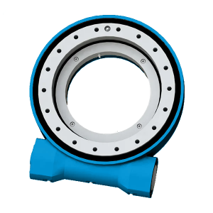
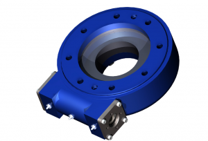
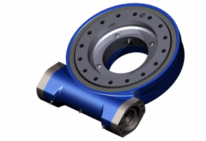
Structure Drawings
- Housing base
- Slewing Ring
- Raceway
- Seal
- Top Plate
- Drive (hydraulic motor /electronic motor)
- Motor Adapter
- O-ring
- Input Hole
- Shaft Opposite to Motor
- End Cap
- Cover
- Encoder

Horizontal Installation
It is advised to mount the slewing drives upside down on the azimuth axis in solar applications for better protection and add protection for the elevation axis. For other applications, the mounting directions shall be based on the evaluation of the protection level and it shall be better for better protection.

Vertical Installation
It is advised to mount the slewing drives referring to attached drawing upside in solar applications for better protection. For other applications, the mounting directions shall be based on the evaluation of the protection level and it shall be better for better protection.