Grid Coupling
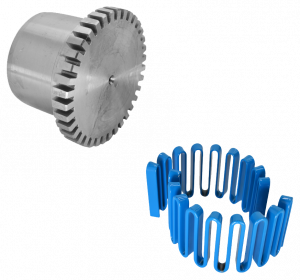
TransDrive Tapered Grid Couplings are compact shaft-to-shaft couplings engineered to deliver high torque capacity, thanks to their robust construction using high-strength hardened alloy steel. The unique tapered grids feature a trapezoidal cross-section and are heat-treated to achieve spring hardness, providing excellent flexibility and shock absorption.
These grids undergo a precision process known as shot peening, where high-velocity steel microbeads compress the surface molecules. This compression significantly enhances the strength rating of the grid and builds in reserve strength, contributing to longer service life and great durability under demanding conditions.
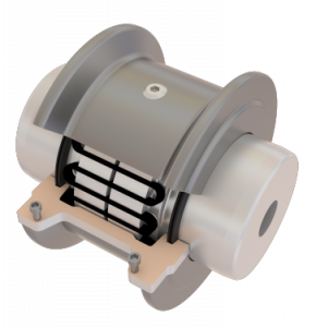
Installation and maintenance are made easy with TransDrive’s removeable cover design, giving quick access to the tapered grids. Unlike rectangular designs, the trapezoidal shape allows for effortless fitting into the hub slots – without the need to move surrounding equipment or cause unnecessary downtime. The coupling’s compact form allows for direct placement of the grids, and the practical split cover can be secured using standard tools, simplifying the process even further.
TransDrive Tapered Grid Couplings combine strength, efficiency, and user-friendly design, making them an ideal choice for high-performance industrial applications.

Protection against Shaft Misalignment
The tapered grids are free to rock, pivot and float within the hub teeth. This provides generous capacity for misalignment without producing the detrimental side loads on the bearings that are often crated when couplings are misaligned.
Protection Against Shock & Vibratory Loads
The Tapered Grid Couplings are able to deflect torsionally when subjected to normal shock or vibratory loads, so they are able to handle changing load conditions. The system truly is a shock absorber for rotary motion, relying on the predictable resilience of the grid for torsional flexibility. The tapered grids “tune” the drive system. Due to their spring hardness, the grids absorb impact by spreading the impact energy over time. The grids can also damp vibration and reduce the peak or shock loads experienced by the rest of the system.
Misalignment Capacity
Accurate alignment results in the maximum life and minimum maintenance for the coupling and the connected machinery. The amount of time for a coupling to reach its maximum operating limits is a function of load, operating speed and lubrication. Maximum operating values listed in the table below are based on the allowable RPM listed on the catalogue. Values listed are based on the use of the specified gaps, use of standard coupling components, standard assemblies and catalogue allowable speeds. Values may be combined for an installation or operating condition. Parallel misalignment is the distance between the centers of each shaft. Angular misalignment is dimension X minus dimension Y as shown in the drawing below. End float is the axial movement of the hubs within the covers as measured from “0” gap. This measure assumes zero angular and zero parallel misalignment.
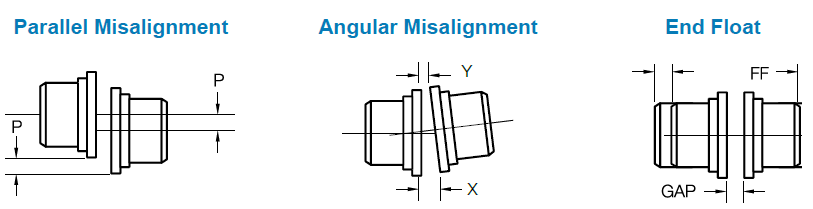
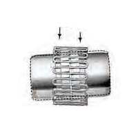
Parallel Misalignment
- The movement of the grid in the lubricated grooves accommodates parallel misalignment and permits full functioning of the grid-groove action in damping out shock and vibration
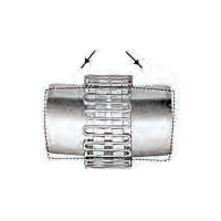
Angular Misalignment
- Under angular misalignment, the grid-groove design permits a rocking and sliding action of the lubricated grid and hubs without any loss of power through the resilient grid
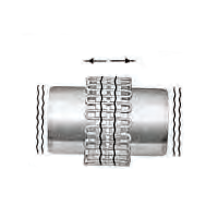
End Floating
- Unrestrained end float of driving and driven members is permitted because the grid slides freely in the lubricated grooves.
Torsional Flexibility
- Torsional flexibility is the advantage of taper grid couplings, providing flexible accommodation to changing load conditions.
Product Specifications
| Coupling Size | Recommended Installation | Operating | Fastener Tightening Torque Values (Nm) | ||
|---|---|---|---|---|---|
| Parallel Offset P Max (mm) | Angular (1/16o) X – Y Max (mm) | Parallel Offset-P Max (mm) | Angular (1/4o) X – Y Max (mm) | ||
| 1020 | 0.15 | 0.08 | 0.3 | 0.25 | 3 |
| 1030 | 0.15 | 0.08 | 0.3 | 0.30 | 3 |
| 1040 | 0.15 | 0.08 | 0.3 | 0.33 | 3 |
| 1050 | 0.20 | 0.10 | 0.4 | 0.41 | 3 |
| 1060 | 0.20 | 0.13 | 0.4 | 0.46 | 3 |
| 1070 | 0.20 | 0.13 | 0.4 | 0.51 | 3 |
| 1080 | 0.20 | 0.15 | 0.4 | 0.61 | 3 |
| 1090 | 0.20 | 0.18 | 0.4 | 0.71 | 3 |
| 1100 | 0.25 | 0.20 | 0.5 | 0.84 | 5 |
| 1110 | 0.25 | 0.23 | 0.5 | 0.91 | 5 |
| 1120 | 0.28 | 0.25 | 0.56 | 1.02 | 6 |
| 1130 | 0.28 | 0.30 | 0.56 | 1.19 | 6 |
| 1140 | 0.28 | 0.33 | 0.56 | 1.35 | 6 |
| 1150 | 0.30 | 0.41 | 0.6 | 1.57 | 6 |
| 1160 | 0.30 | 0.46 | 0.6 | 1.78 | 6 |
| 1170 | 0.30 | 0.51 | 0.6 | 2.01 | 6 |
| 1180 | 0.38 | 0.56 | 0.76 | 2.26 | 6 |
| 1190 | 0.38 | 0.61 | 0.76 | 2.46 | 6 |
| 1200 | 0.38 | 0.69 | 0.76 | 2.72 | 6 |
Selection of Puller Holes
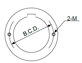
| Coupling Size | B.C.D (mm) | Bolt Size |
|---|---|---|
| 1070 | 74 | M8 |
| 1080 | 89.5 | M8 |
| 1090 | 106 | M10 |
| 1100 | 121.5 | M10 |
| 1110 | 136.5 | M10 |
| 1120 | 150.5 | M12 |
| 1130 | 185 | M16 |
| 1140 | 205 | M16 |
| Coupling Size | B.C.D (mm) | bolt Size |
|---|---|---|
| 1150 | 227.5 | M20 |
| 1160 | 260 | M20 |
| 1170 | 306 | M24 |
| 1180 | 341 | M30 |
| 1190 | 373 | M30 |
| 1200 | 414 | M30 |
| 1210 | 540 | M30 |
| 1220 | 570 | M30 |